Lidar
Lidar sensor in Marus simulator is implemented using Raycast feature. The script generates array of rays pointing at directions that are calculated based on given sensor parameters. Rays are then cast and poincloud is generated.
Initializing lidar object
As with all sensors, the best way to organize your setup on the vehicle is to create new game object and place it under Sensors parent object on your vehicle. Having independent object for lidar gives you the ability to easily move and place sensor on the desired position on your vehicle or vessel.
To actually get lidar capabilities, you must add the RaycastLidar component to the previously created lidar GameObject.
Configuring sensor parameters
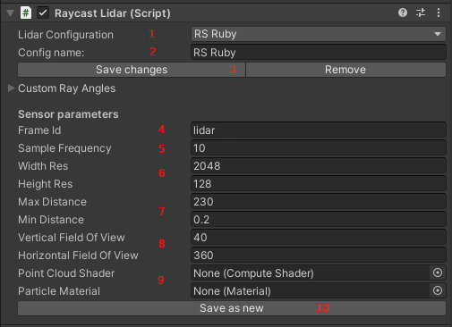
Once you’ve added the RaycastLidar component, you will see the inspector menu with default parameters.

On the image above you can see several sections of configuration window:
1 - Picklist for selecting one of the available configurations
2 - Configuration name, for editing the name or for purpose of creating new configuration
3 - Save & Remove buttons
4 - Frame Id - string name of frame id, used for ROS message header (explained in detail later)
5 - Sample frequency in Hz - how often to generate new points
6 - Width & Height Resolution - Number of rays for each dimension
7 - Maximum & Minimum Distance of lidar rays
8 - Vertical & Horizontal field of view - in degrees
9 - Material and Shader properties for visualization
10 - Button for saving configuration as a new one
For any change you make to configuration, you should save them by clicking the Save changes button or Save as new if you wish to create a new one.
Out of the box there are several configurations available for you to use:
Uniform This configuration serves as a basis for creating your own configurations with uniform distribution of the rays. This means rays will be distributed uniformly with respect to angle between them.
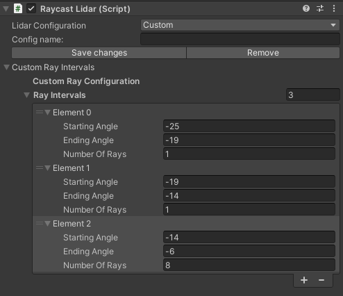
Custom This option enables you to define your own rays distribution pattern. Once you’ve selected the Custom option, the Custom Ray Intervals submenu will appear. If you click on the little arrow on the left, the menu will expand and you will be able to configure your custom lidar. If you expand the next section called Ray Intervals and click on the plus icon, you can start inputing lidar ray distribution parameters.

On the image above, you can see the first three defined intervals taken from the Pandar64 lidar user manual. Input the intervals by starting with the lowest angle and move up. If the values do not make sense, the script will warn you so you can fix it right on the spot.
Once you’ve configured the ray distribution, you can set other parameters as you wish and hit the Save as new button. Don’t forget to input the name for your new configuration. After you save it, the configuration will appear as a new option in the picklist menu.
RS Ruby, Pandar64, Ouster These configurations use parameters and configurations from real sensors available in the market.
Acquiring and visualizing the pointcloud data
For each object you want to be visible by lidar, you have to assign it a Collider component. This is needed because the Raycast feature in Unity uses colliders to detect collisions with other objects.
Streaming pointcloud data to ROS
As with all other sensors, you can stream lidar data to ROS by using grpc_ros_adapter package. For getting started with ROS streaming, visit the ROS Getting Started page.